Motor Dyno (Ongoing)
Introduction#
Basically every motor manufacture is outright lying about what their motors do. At absolute best, they’re providing a spec that is maybe achievable for seconds.
For example, you might find a motor rated for “5kw”. 5kw for how long? At what voltage? At what current? These sorts of specs are borderline useless, but generally the best you’re going to get. KV is also usually provided, which at least gets you to some bare idea of speed.
For a basic vehicle project, generally you want to know how much torque a motor can provide, how long it can provide it, and how many amps are required to achieve it. Efficiency is also handy.
You can use the few published numbers and the volume of the motor to take some guesses, and this is often good enough for speccing out something basic like a scooter, or something with very similar motors like a quadcopter (drone motor performance can be compared with fair accuracy solely by stator volume). But when you need real numbers, you have to test them yourself. This is where a dyno comes in. All a dyno does is run a motor under a series of different speed and torque conditions and records the current, voltage, torque, and speed.
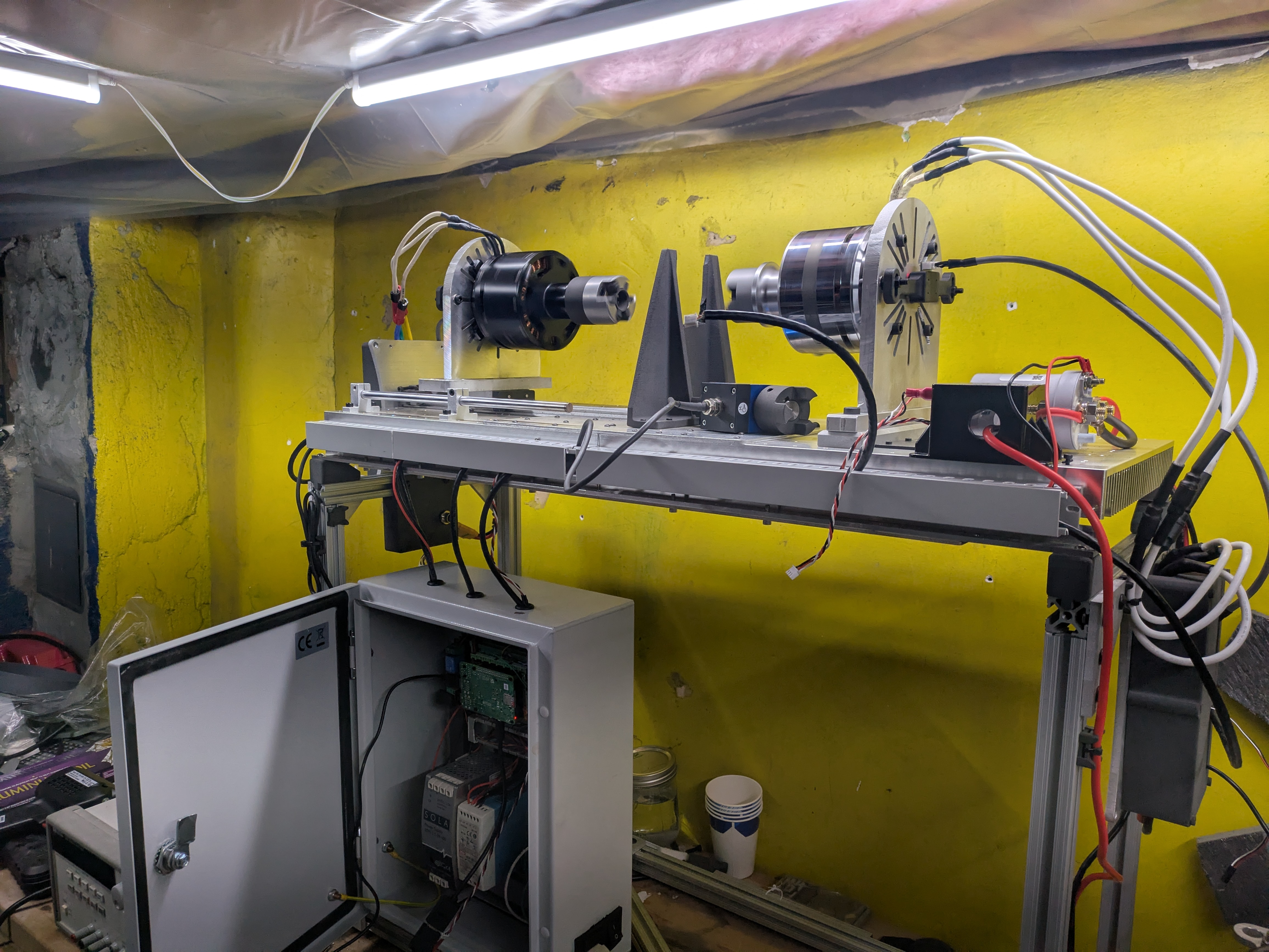
This particular kind of dyno is a “regen dyno”. Power is just Torque*rotary velocity, and that power needs to go somewhere when the motor is being tested. Dynos accomplish this in a variety of ways including dissipatting it in fluid, using magnetic braking and dissipating the heat, using friction braking and dissipating the heat, running the motor into a generator and dissipating the current as heat in a gel. A regen dyno uses two motors that “fight” each other. One is being tested, the other acts as a generator and returns the power back to the battery. Because the relentless forward march of time, some energy is still lost to entropy and dissipated as heat.
State of the Project#
Currently, every part of the dyno works. The only thing left to do is to write a script to get the main computer to run through a speed/torque sweep and gather data. This writeup is also still a bit rough.
Electronics#
System Diagram#
Power distribution
Control and sensing
Control Box#
I worked as a test engineer at Formlabs from around 2023-2025, so I got very used to their internal server setup. Formlabs printers are all running Raspberry Pis internally, and we just run python scripts on them to get anything test-related done. I set up the main control box for the dyno the same way - raspberry pi at the heart of everything talking to the sensors and the motor controllers.
To keep everything neat, I got very into DIN rail. DIN, in my opinion, is underused in the hobby space because the components are dirt cheap when purchases used and they go a long way towards cleaning up the usual wiring mess. I was even able to find a DIN rail mount rapsberry pi case with terminal blocks.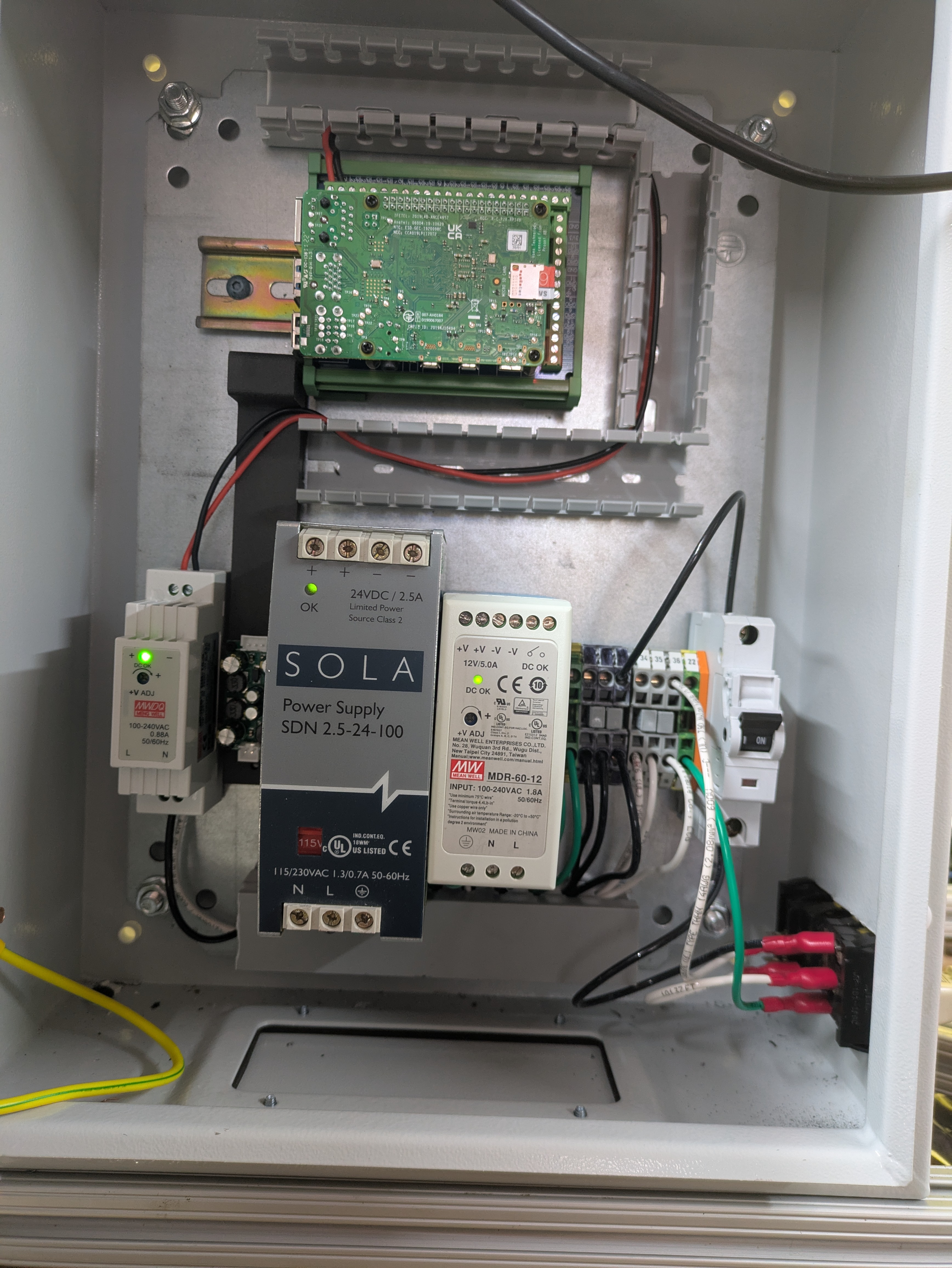
Current Sense#
I needed a way to measure the 200+ amps on the battery bus. This is somewhat above what your typical shunt resistor can handle. There is a little known cousin to the transformer that can help with that, the current transformer. This is a 2000:1 transformer, so that 200amps to the motor controllers becomes 0.1 amps on the other side of the transformer. Simple enough, and these are inductive style transformers so the battery lead is just routed through the sensor. Finally, this all goes to a small, custom board I made up that reads the transformed current by measuring the voltage drop across a shunt resistor.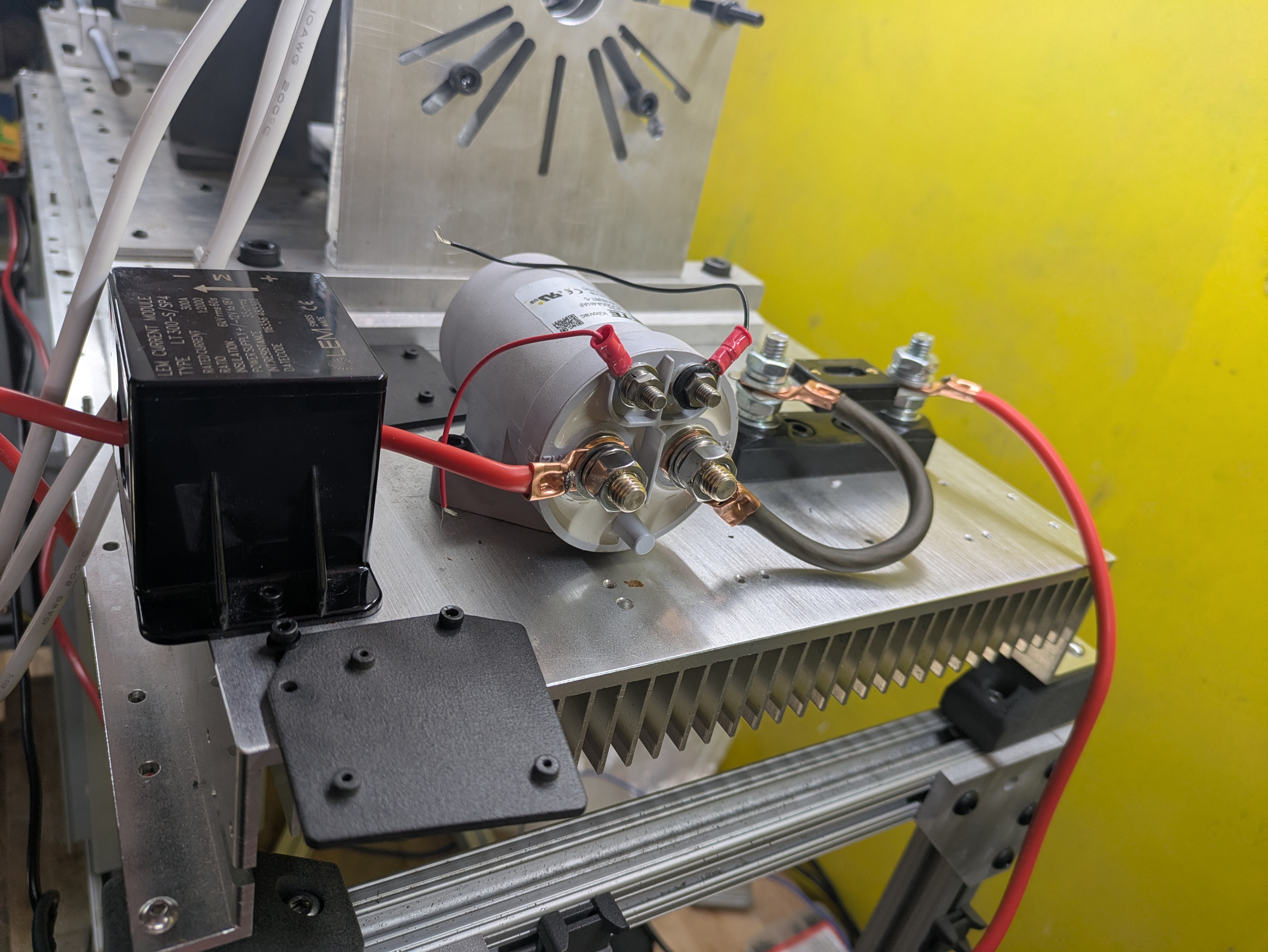
Torque Sensor#
There’s basically three kinds of torque sensor: -prony brake style, basically a lever arm with a load cell on the end. -reactive torque sensor, rigidly mounts behind the motor and does not spin. Decent, but not the most accurate -rotary torque sensor, a load cell with a rotary coupler that reads torque while spinning. This is the most accurate and the most expensive. I bought mine on ebay.
These torque sensors often need an amplifier to read the the minute analog voltage signal. However, I was able to find one with a built in amplifier that has a reasonably readable voltage range. I did have to spin up a custom analog to digital converter PCB to talk to the main computer, but this was easier than doing real analog electronic design.
MOTOR CONTROLLERS#
Theory of Operation#
The brushless motors need controllers. I won’t go deep into theory here, but essentially a brushless motor controller, also called an Electronic Speed Controller (ESC) or Inverter, is an electronic device designed to supply a controlled current to each of the three phases of a motor. The key sections of a brushless motor controller are the inverter bridge, the gate drivers, current sensors, and the MCU. Sensored motor control also requires some sort of positional sensor.
I’m using VESCS, which are programmable motor controllers derived from the Benjamin Veder Open Source ESC project. Programmable is important because I’ll need to use these with other motors. They’re also controllable over CAN, which is okay for interfacing with the main control computer.
The Motor Controller of Dubious Quality#
Motor controllers are still outside of my electronic design skills at the moment, so I purchased or was given a set. Specifically, I used the Flipsky 7500. These are VESCS that, if nothing else, are a lot of amps of controller for very cheap. Cheap, as always, has other costs. I’ve never had issues with Flipsky controllers blowing up on me, but there are some signs of questionable quality; visible bodge jobs, low quality capacitors, and questionable electronic design choices. But again, cheap.
Since I didn’t have the aluminum enclosures for these controllers anymore, I used some aluminum plates I had sitting around and printed a plastic cover from TPU for electronic protection. Then I bolted the whole assembly to either end of the dyno frame.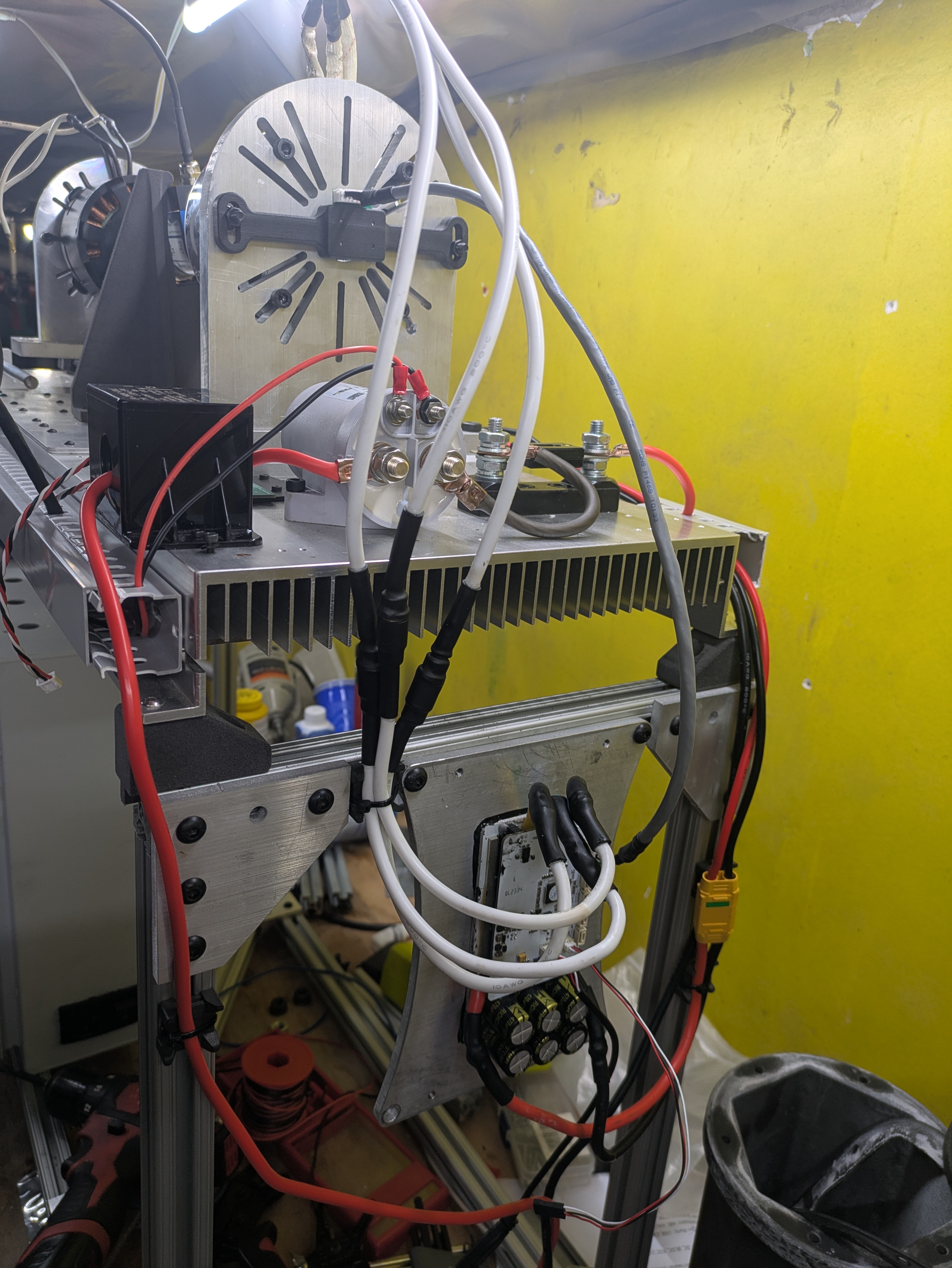
Encoder Woes#
As I mentioned, brushless motors can be run with or without sensors. I want full, closed loop control so I’ll need some sort of sensor. Hall effect sensors are typical for vehicles that don’t need very high precision, but I have some robotics interests so I went with a proper magnetic encoder.
Magnetic encoders read the angle of a diametrically polarized magnet. I’m using drone motors for this project which are usually intended to be used sensorless, so I added a small adapter to mount a magnet to the rear of the motor and a 3D printed encoder mount to the back side of the motor mount.
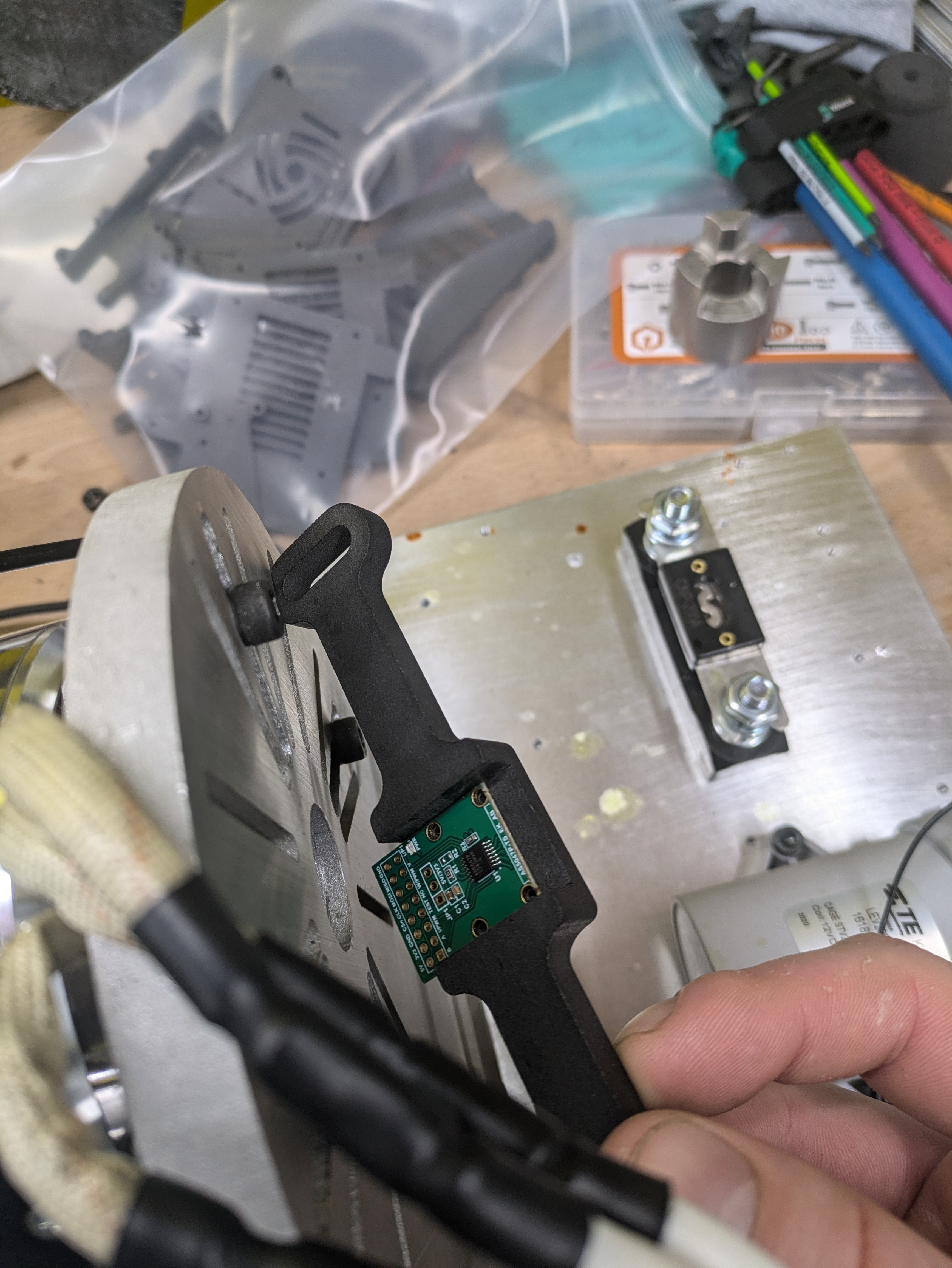
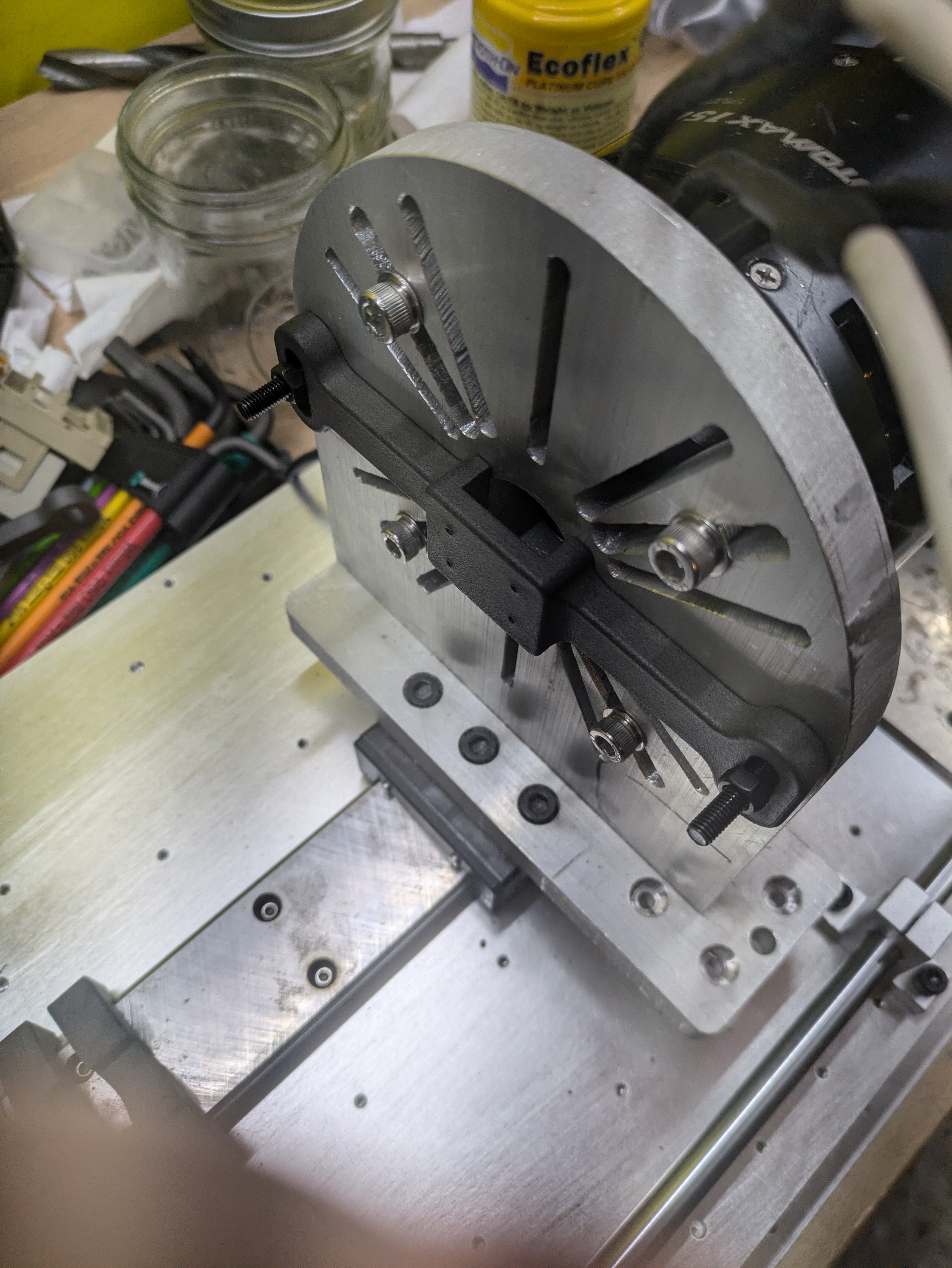
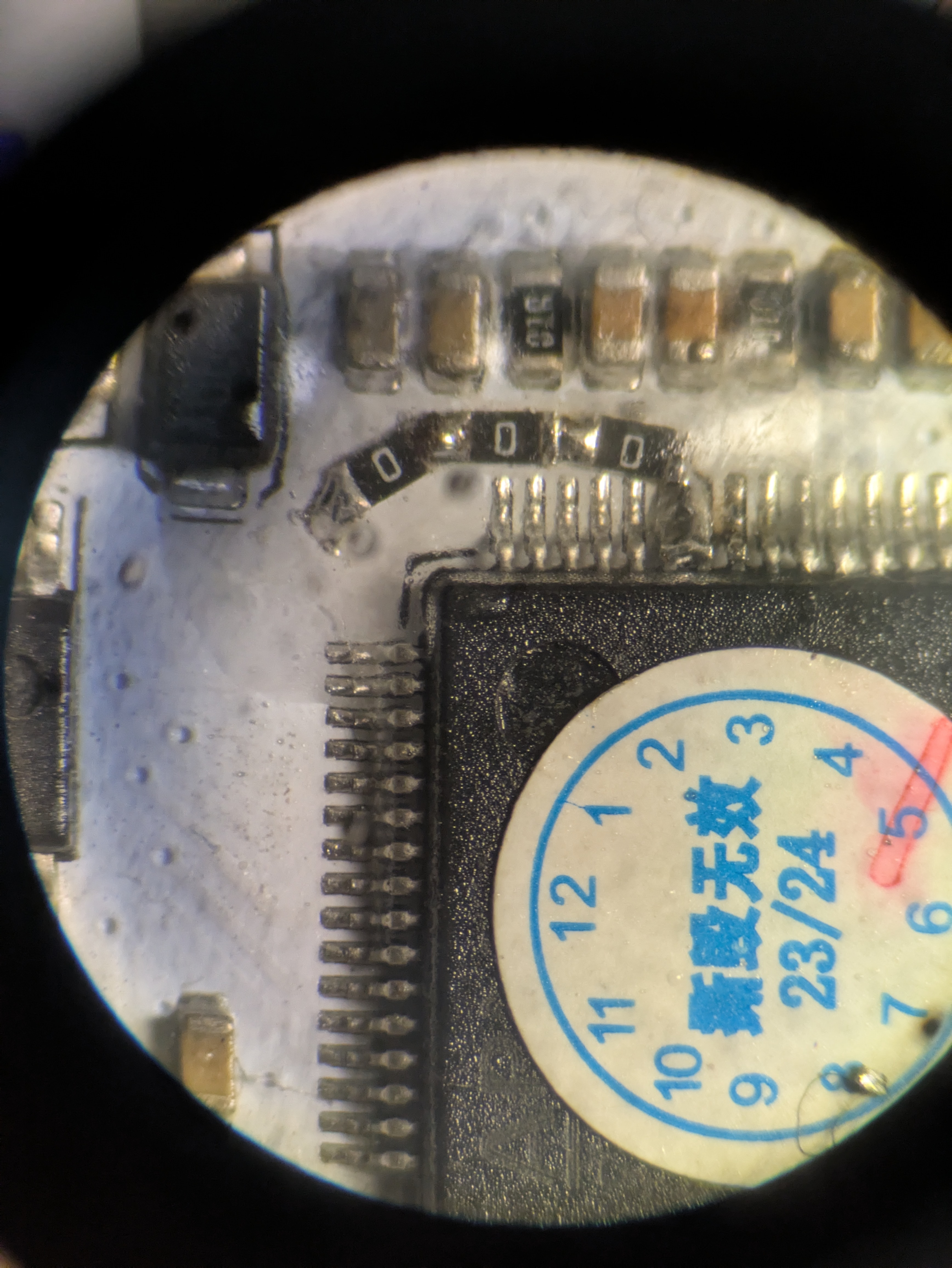
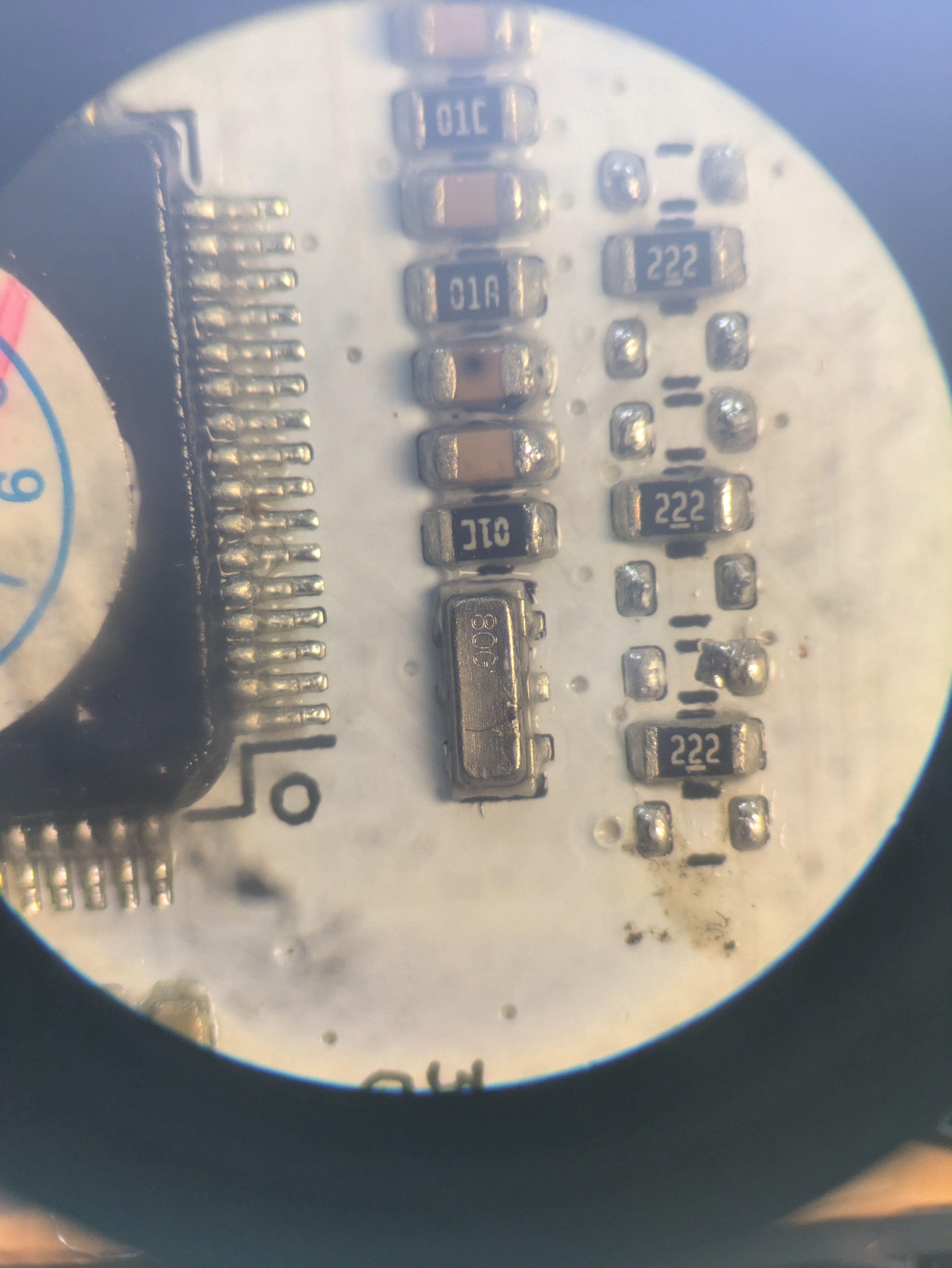
I had wired the encoder with some spare ethernet cable I had around, but SPI isn’t technically intended as wired communication protocal. It isn’t very noise resistant, because it’s only really intended for use on the same PCB for component level commumication.
In order to get the encoders working correctly, I ran out to my local MicroCenter (praise be to MicroCenter, I miss it already), and purchased at great expense some short shielded ethernet cables. I actually went through the trouble of using twisted pairs and grounding properly, and this cleaned up the signal enough to get the encoders working flawlessly.
Mechanical Setup#
A few requirements of the motor dyno:
- Measure torque
- React torque
- Accommodate a variety of motor lengths and diameters
Overconstraint#
A key factor here is an engineering principle called overconstraint. Essentially, a motor is a stiff system with at least two bearings in of itself. If you try to add a third bearing, you’re basically guaranteed to be misaligned and this misalignment generates enormous forces on the shaft. To put it another way, think of just a shaft. Place a bearing on one end and this constrains the location of the shaft but has relatively little ability to react a moment on the shaft. Add a second bearing, and now you can react moment. Add a third bearing, and now the shaft has to cyclically bend to accomodate any misalignment in the bearings. This is overconstraint.
—0———————————0—
—0—————-0—————-0—
See above for an incredibly detailed rendition of a shaft and bearings
Okay, so why do you care? Well theres two motors, each with two bearings. And they’re bolted to each other and then to a rigid base plate. Four bearings where there should be two. To make things worse, there’s a torque sensor between them that is very unhappy getting bent. The solution: couplers that can tolerate misalignment. Specifically, I used jaw couplers. These are basically a dog clutch with a rigid elastomer between the teeth to take up backlash. Each coupler is stiff to displacement and torque, but low rigidity to bending. In other words, each coupler can handle some amount of angular misaligment. One coupler is not enough because there is also displacement misalignment between the two motors. With two, the couplers can zig and then zag to turn angular misalignment into displacement.
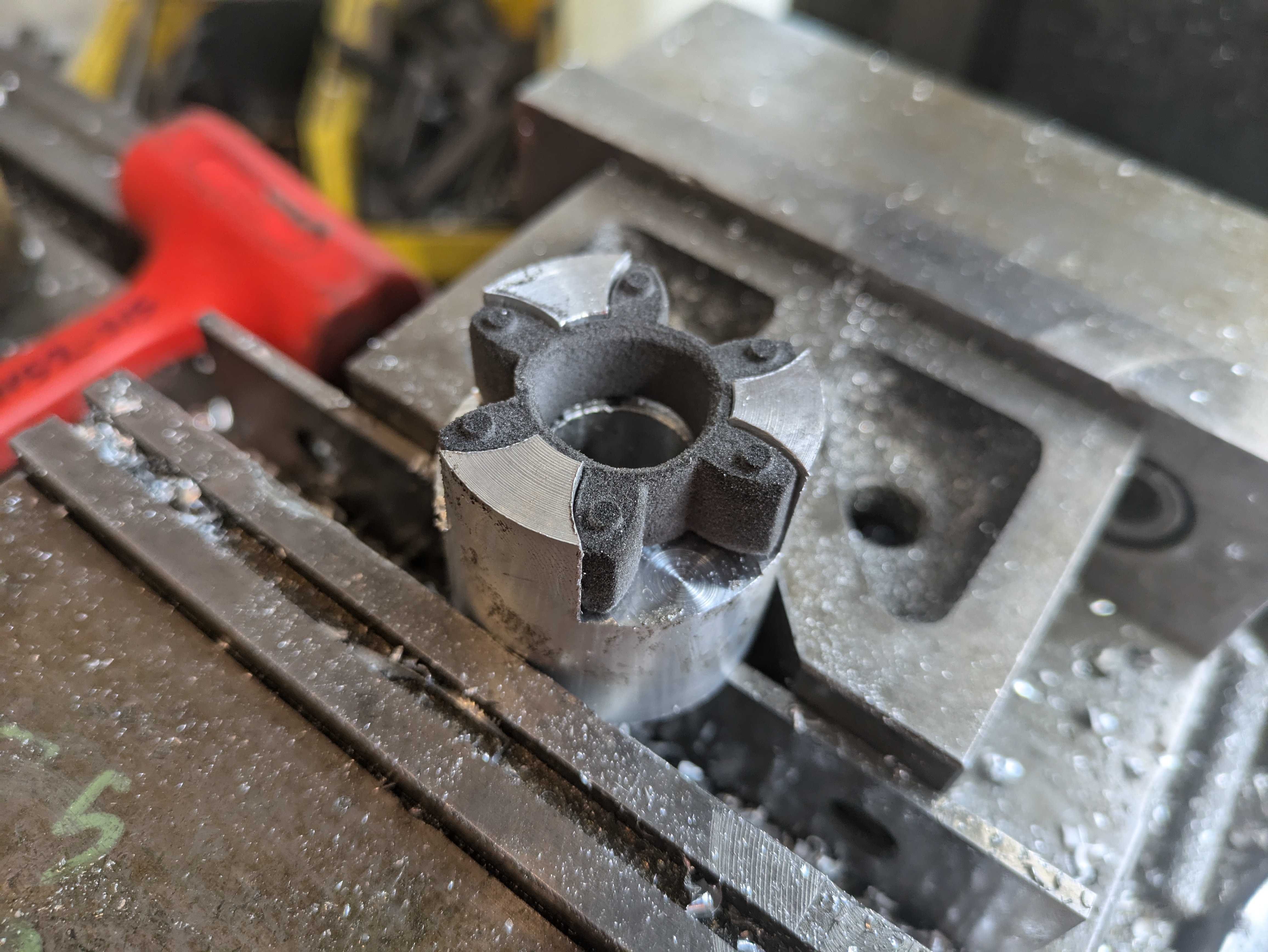
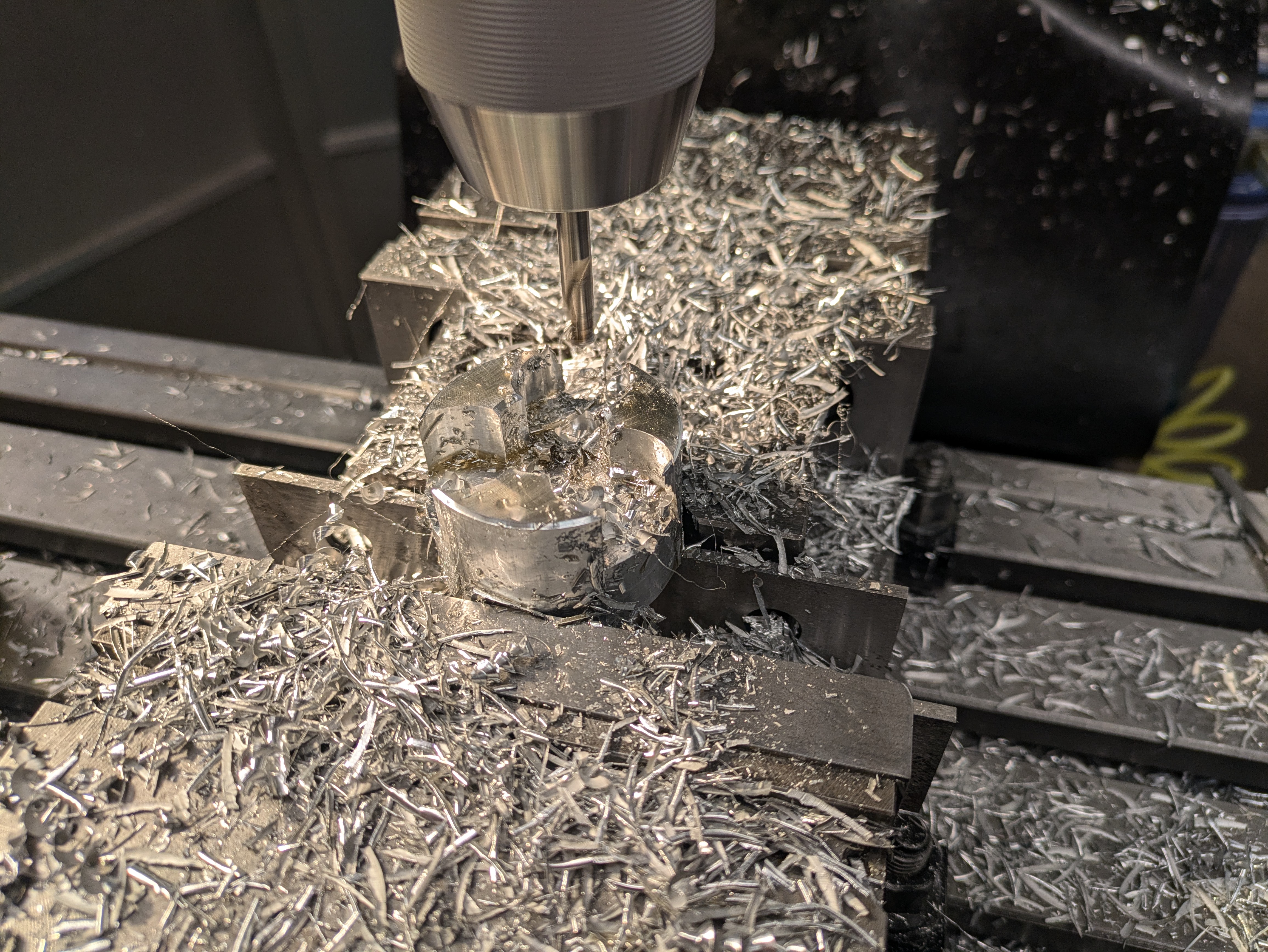
These are expensive so I made them on a prototrack. The elastomers can actually be purchased separately, but mcmaster releases their 3D models and at the time I was working for a 3D printing company that could sinter TPU rubber…
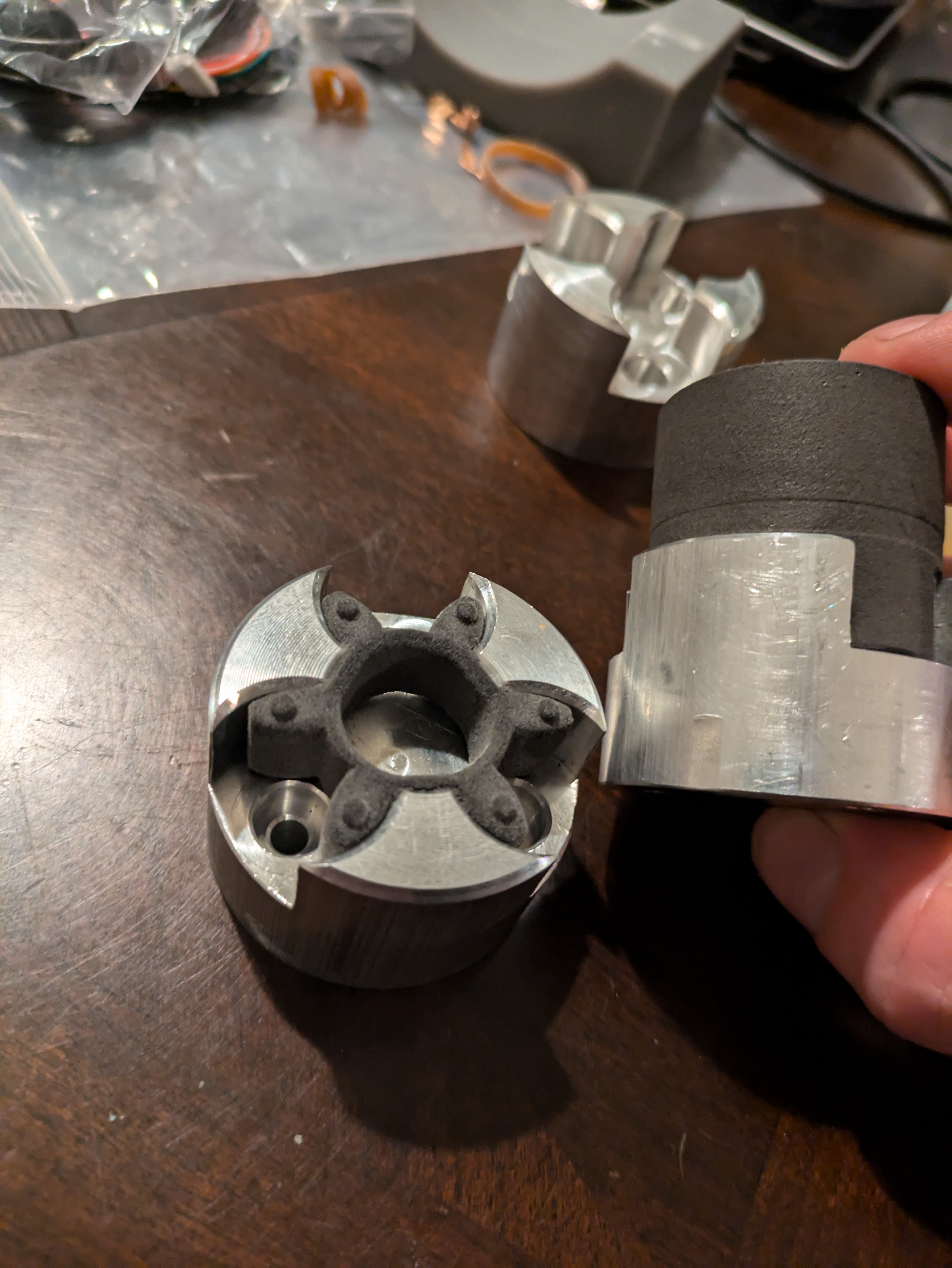
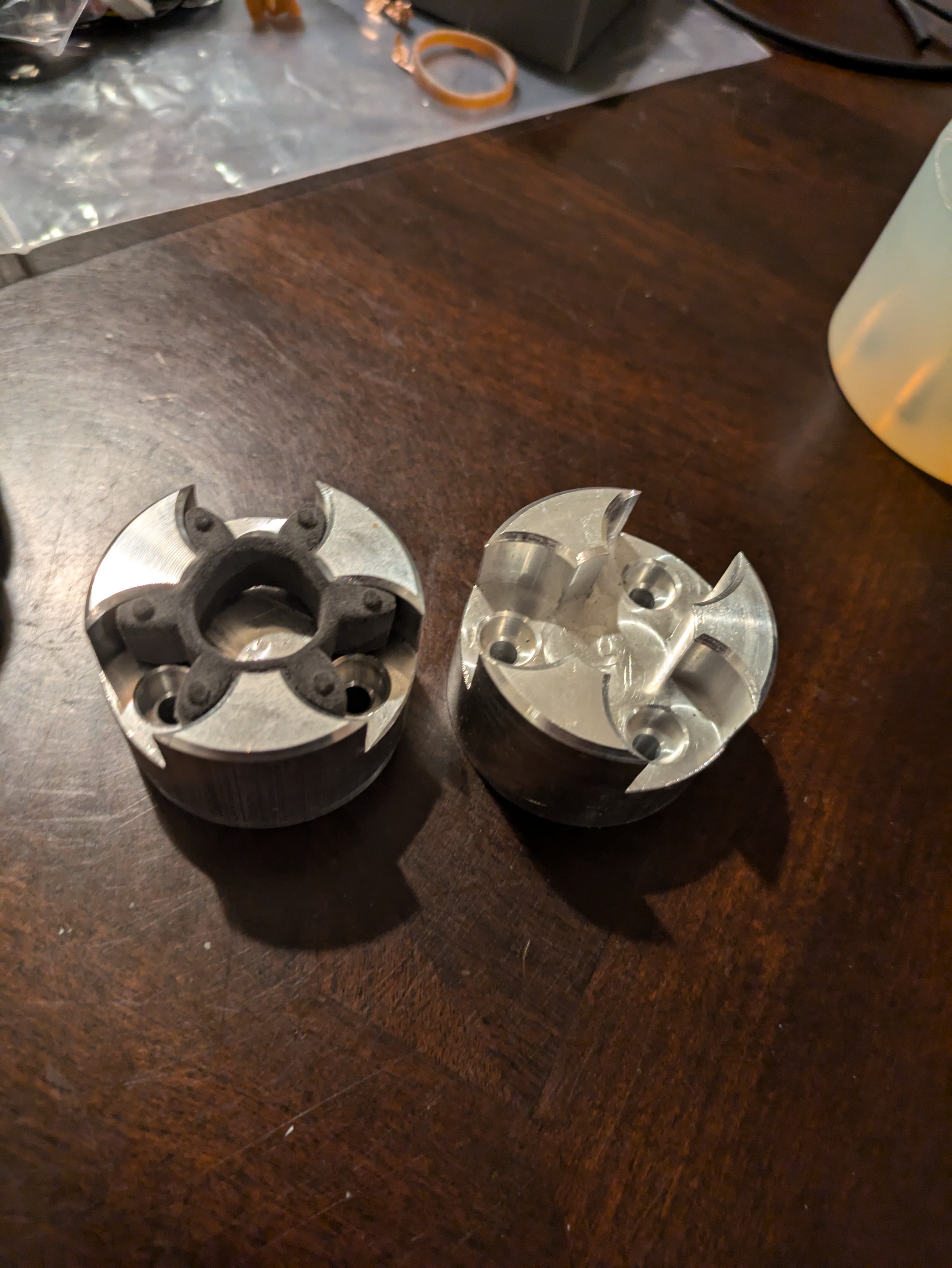
There is one other source of overconstraint here, that being the torque sensor itself. It is possible to rigidly mount the sensor as well, but this requires an aditional set of couplers as the torque sensor adds another two bearings. I’ve opted to avoid that and simply added a rubber support to keep the torque sensor from spinning widly. This does mean there is backlash in torque measurement, but as long as the direction does not change, this is not an issue.
React the torque#
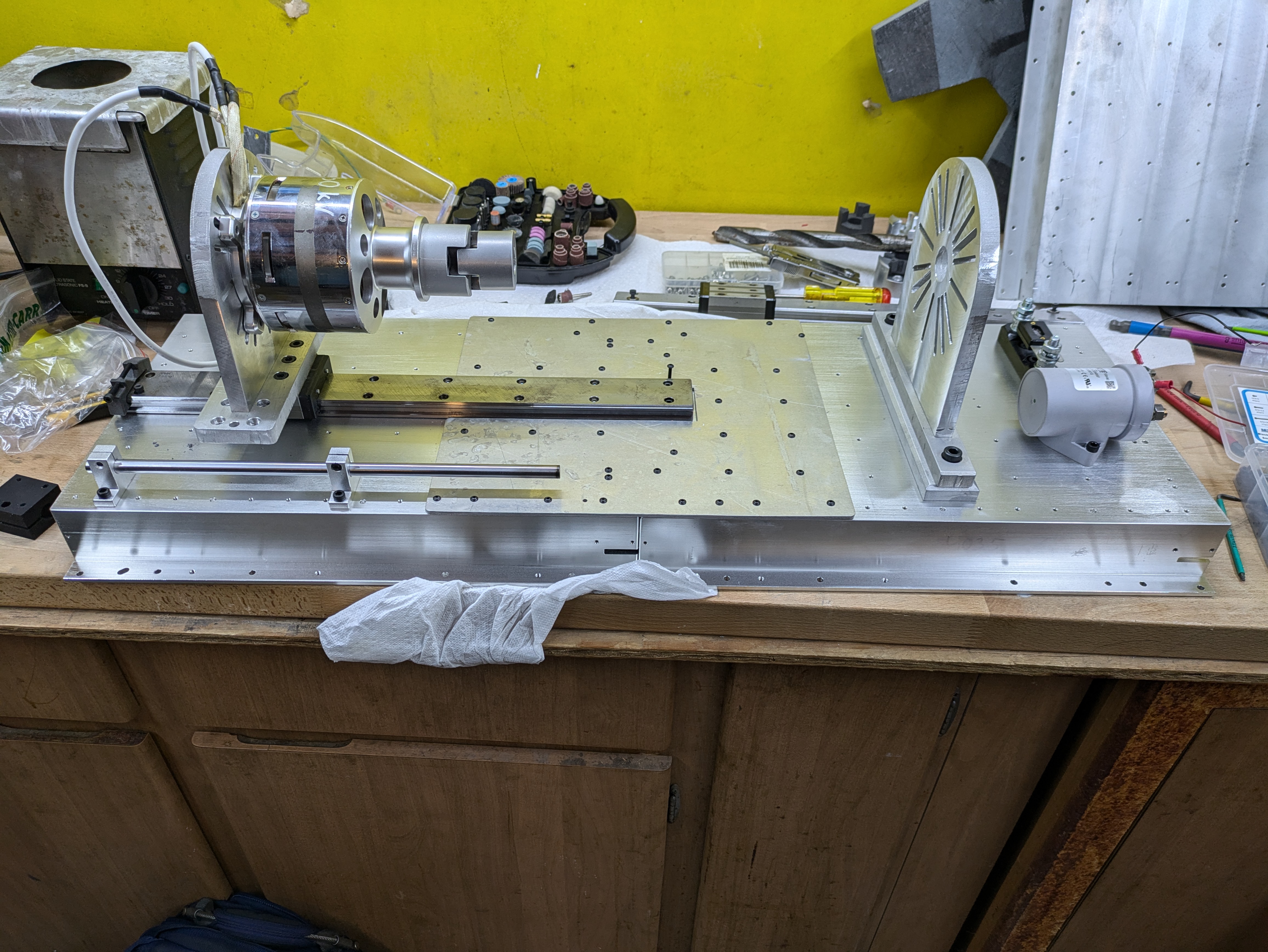
Great, that takes up torque sensing and misalignment. Next is a large linear bearing to handle different motor lengths. Unless I only ever wanted to test a single motor, the motor dyno needs to be adaptable to different motor can lengths. I had some concerns about the ability of the linear motor to hangle the motor torque, but the actual specs of large HTK bearing is pretty absurd. mine in particular would be good up to about the engine torque of a 1970s Firebird, a unit I use only because my roomate’s was available in the garage for comparison at the time. This bearing was sourced from a scrapped Formlabs Form 4, which use these formidable bearings to deal with the considerable force needed to force resin into a thin film.
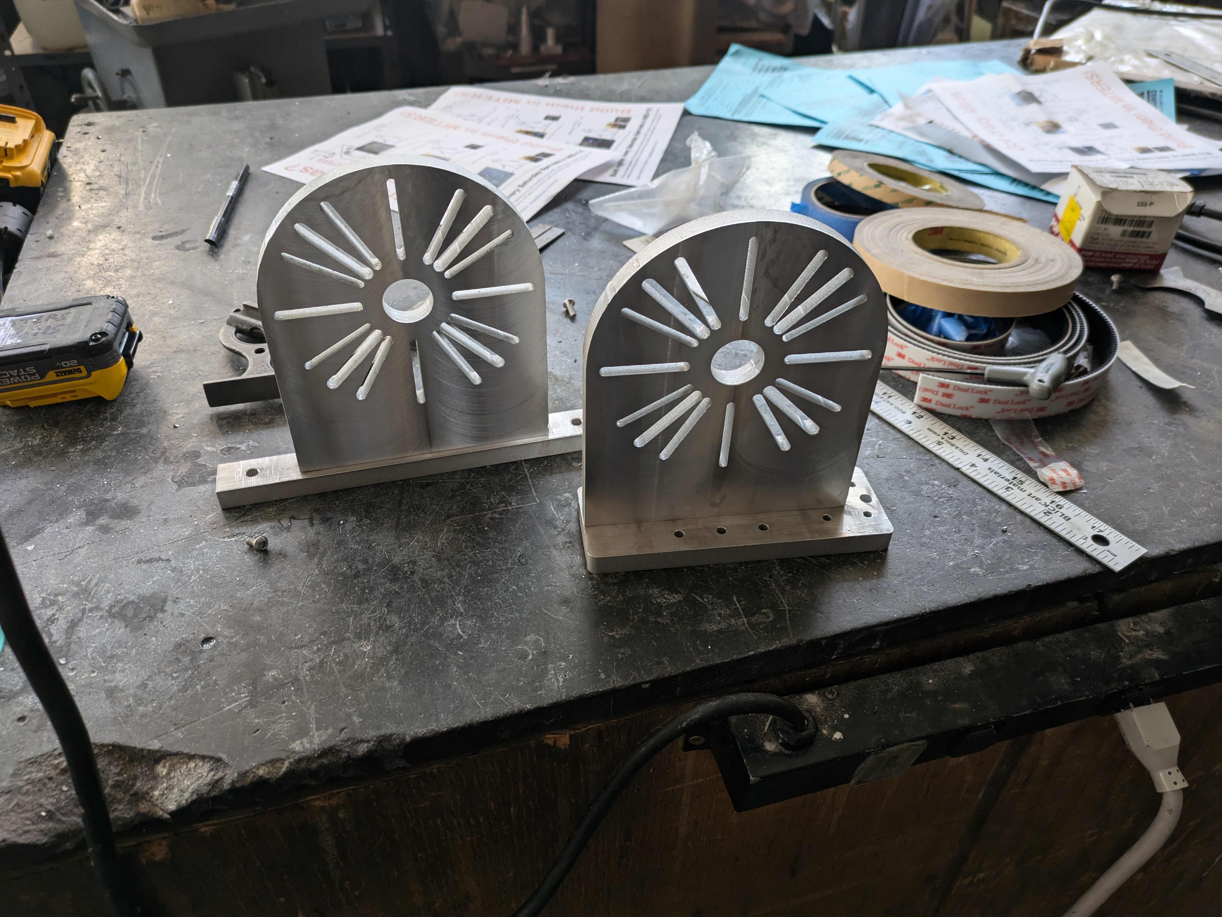
Different mounting setups are accomodated by the waterjet slotted mounting plates.