Introduction#
My last semester at MIT was unpleasantly rushed and I didn’t have time to properly close out this project. So, three years later, I’m writting up my favorite research project here.
MIT is one of the institutes that still uses physical test tanks and scale models to determine the hydrodynamic performance of various projects. I used a towing tank, which is essentially a CNC gantry mounted on top of a large aquarium combined with some very sensitve force transducers. Traditionally, towing tanks like the Intelligent Towing Tank at MIT Sea Grant would have been used to tow a scale model of a ship hull through a large tank of water and measure the resulting forces. Sea Grant has used it for a variety of projects including my hydrofoil project, whisker sensing projects, shoreline protection structure evalutation, etc.
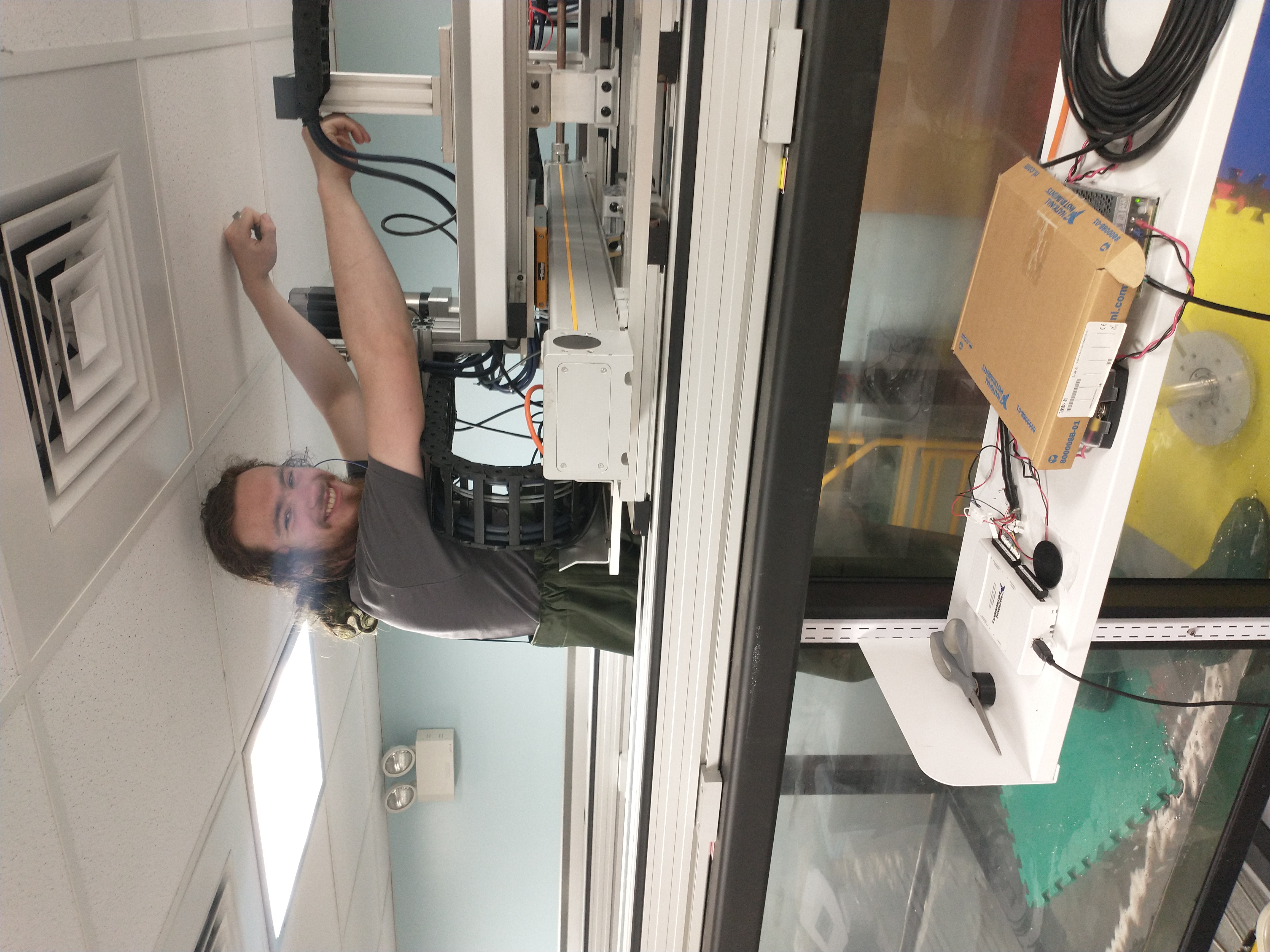
When I started at Sea Grant the Intelligent Towing Tank hadn’t been used for seven years. The control software had issues, the tank itself was dirty, the towing gantry was missing parts, the six axis force/torque transducer was not reading properly, and the computer had been infected by Chinese malware.
Objectives#
My advisor was Dr. Michael Triantafyllou, the director of Sea Grant. He was in contact with The Wake Thief, a youtuber and engineer involved in pushing the limits of human pumped foil board endurance. My job was to analyze videos of human foilers, replicate their motion in the towing tank, and determine the current efficiency through experiment to compare to the theoretical efficiency limits
Background#
Couple of definitions relevant here:
- Hydrofoil: a lift producing structure used underwater. As in, a wing but wet
- Foil Board: a surfboard with a hydrofoil sticking out under it
- Pumping Foil: a hydrofoil that generates thrust through oscillatory motion
Pumping foils are interesting. Traditionally, foils generate lift upwards, but angling a foil can actually vector that lift force to produce thrust. With a human pumped hydrofoil, the rider leans forward and pushed the board down, this tilts the foil in the thrust producing direction and increases speed, created a forward thrust. Then the foiler can tilt back, pop back up, and reset for the next pump.
Towing Tank Repair#
Software#
I can’t take much credit for most of the software fixes. An older grad student migrated the computer away from the infected hardware. I got the load cell talking to some example LabView scripts, but he was able to fully integrate the the data collection into the towing tank control.
What I did do was find and correct an error in the tow tank system. The tank was set up to run through a synusoidal motion. Essentially, you could define a magnitude and frequency and the software back end would generate the appropriate sin function. This would give the required positional control, but the motor control section of the controller also required a velocity input. The sofware would simply take the derivative of the cosine function and feed that into the motor controller. However, it wasn’t deriving correctly. It should be: $$\frac{d}{dx}\cos(x) = -sin(x)$$, but the scrypt was written as $$\frac{d}{dx}\cos(x) = -cos(x)$$
Rotary Axis#
The towing tank doesn’t actually have a Z axis. To replicate the hydrofoil pumping motion, I turned the foil on its side and pumped horizontally. However, I still needed a rotary axis about the z direction to allow for that characteristic tilting.
This was the previous towing tank setup. I’m not entirely sure what structure they were testing, but they didn’t need rotation. The rotary motor is still there, but the mount itself is entirely rigid.
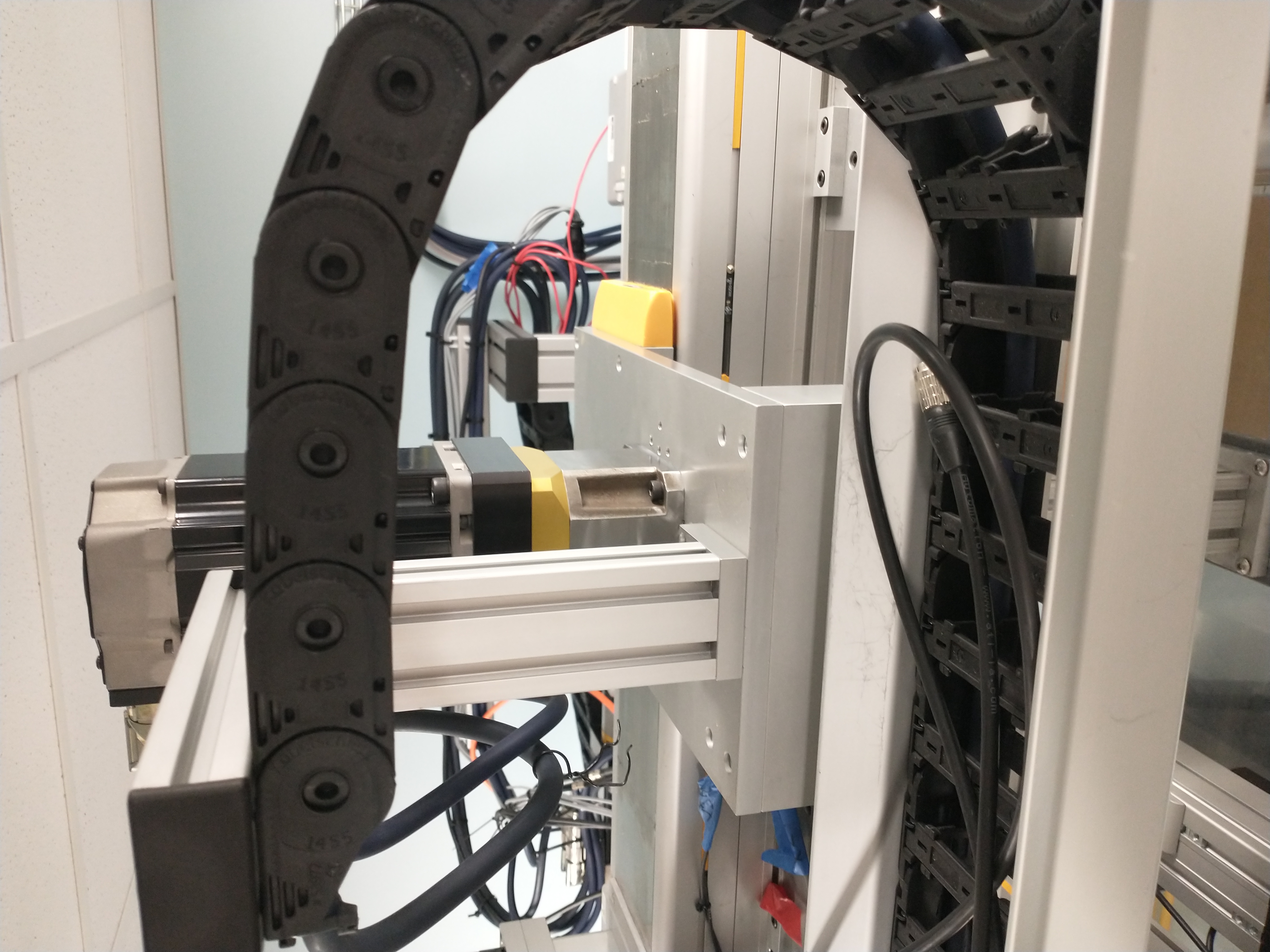
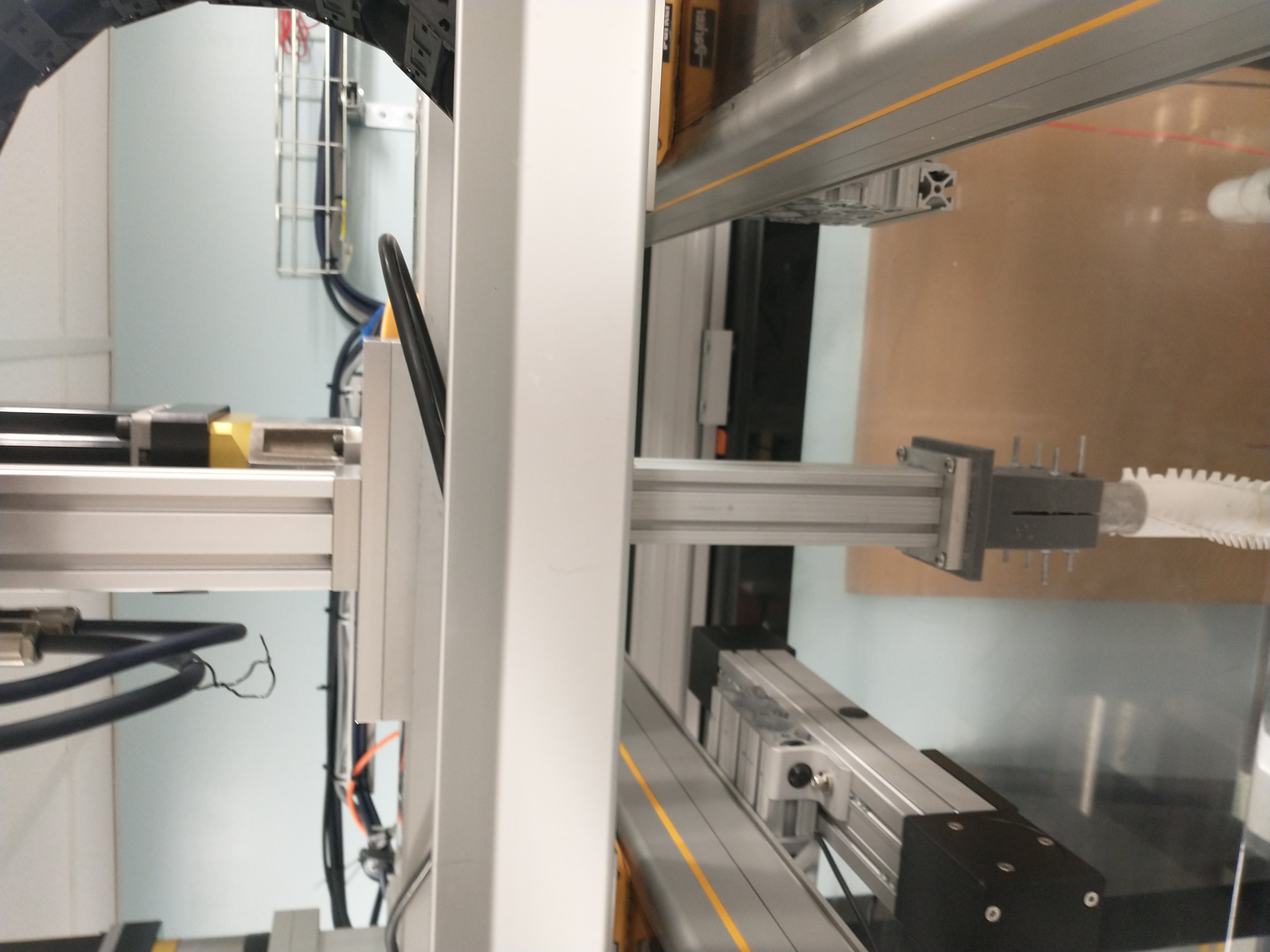
Here you can see the where the rotary shaft passes through the motor mounting plate and how the rotary shaft is mounted on the motor.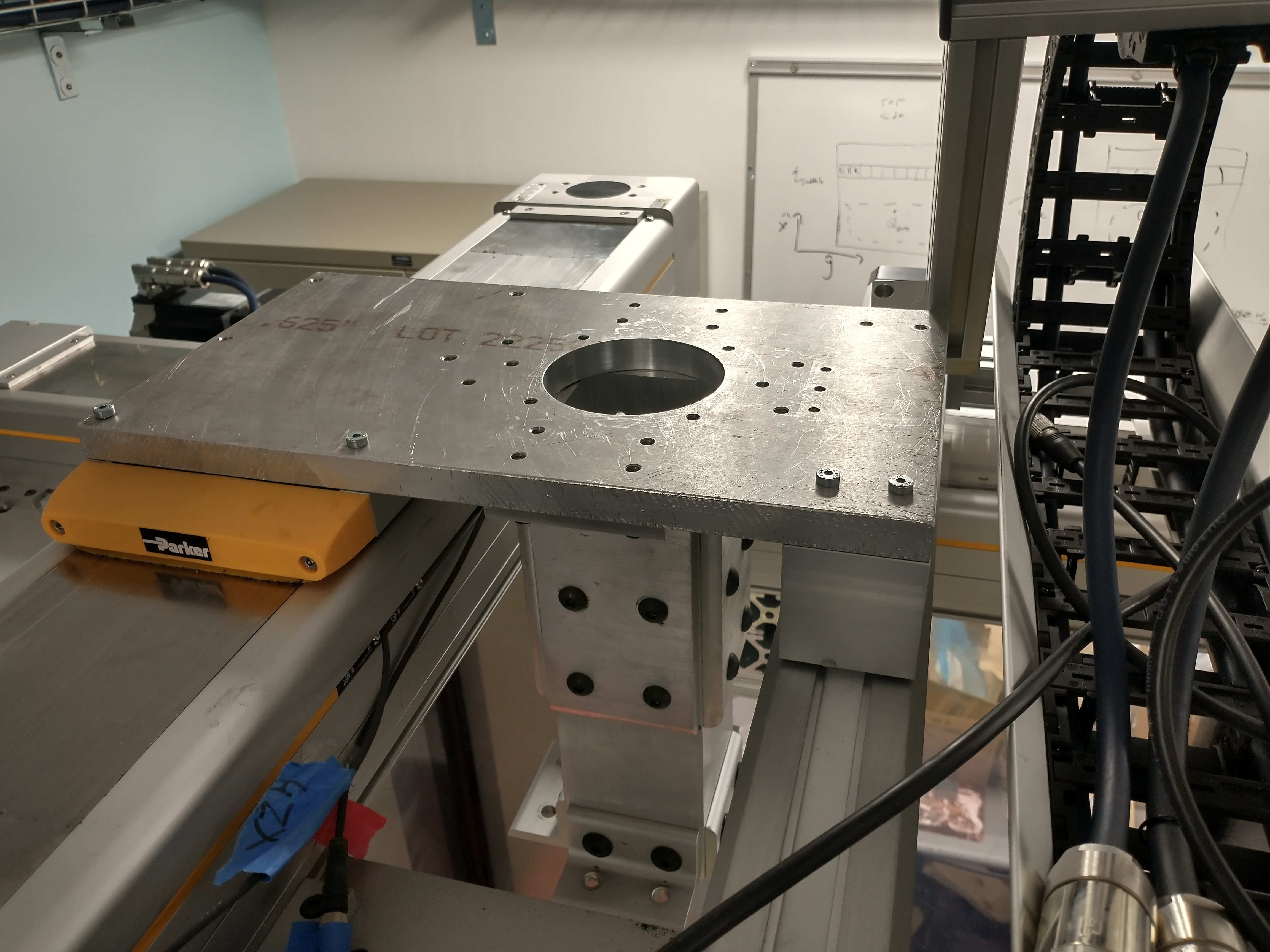
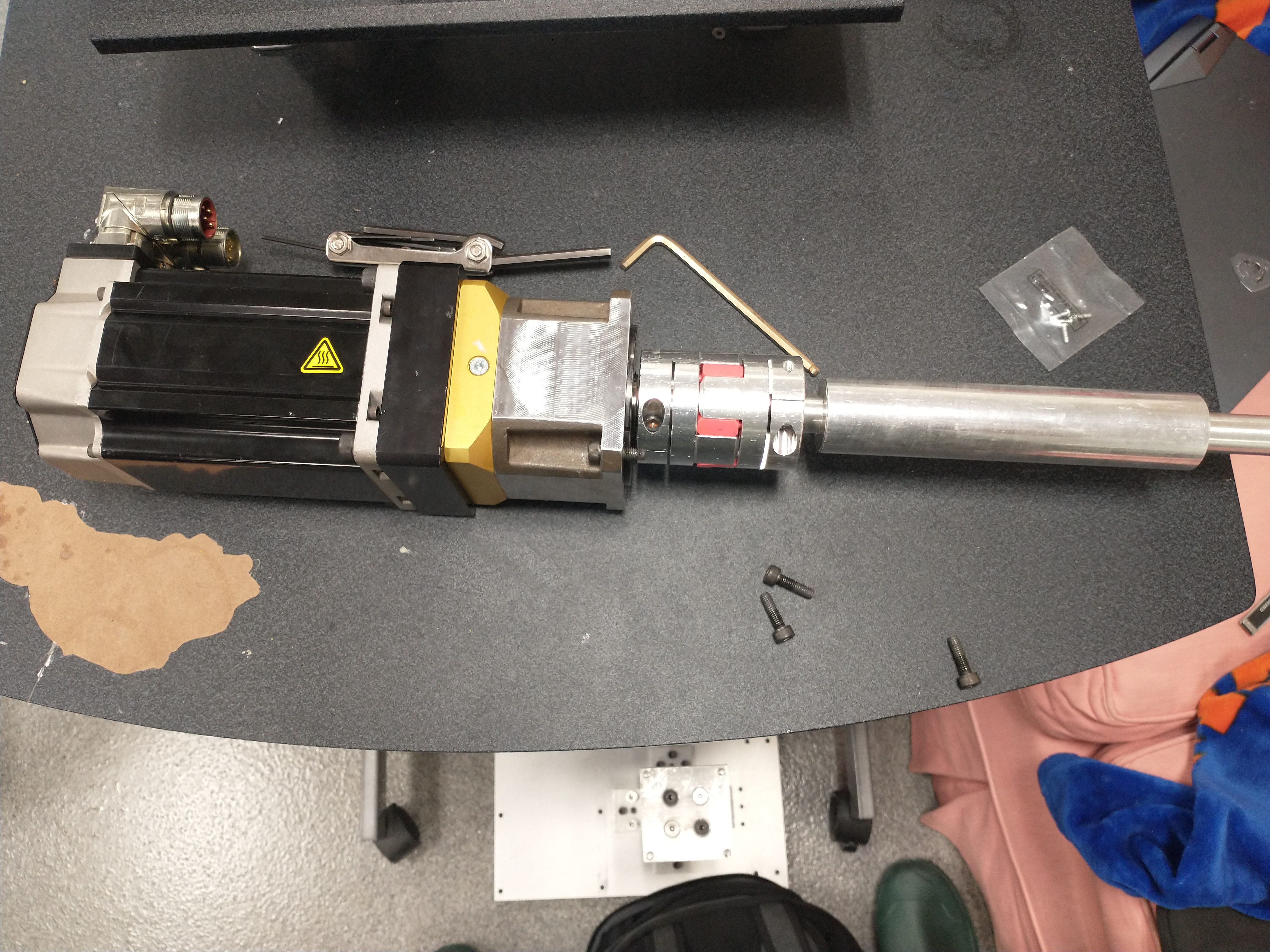
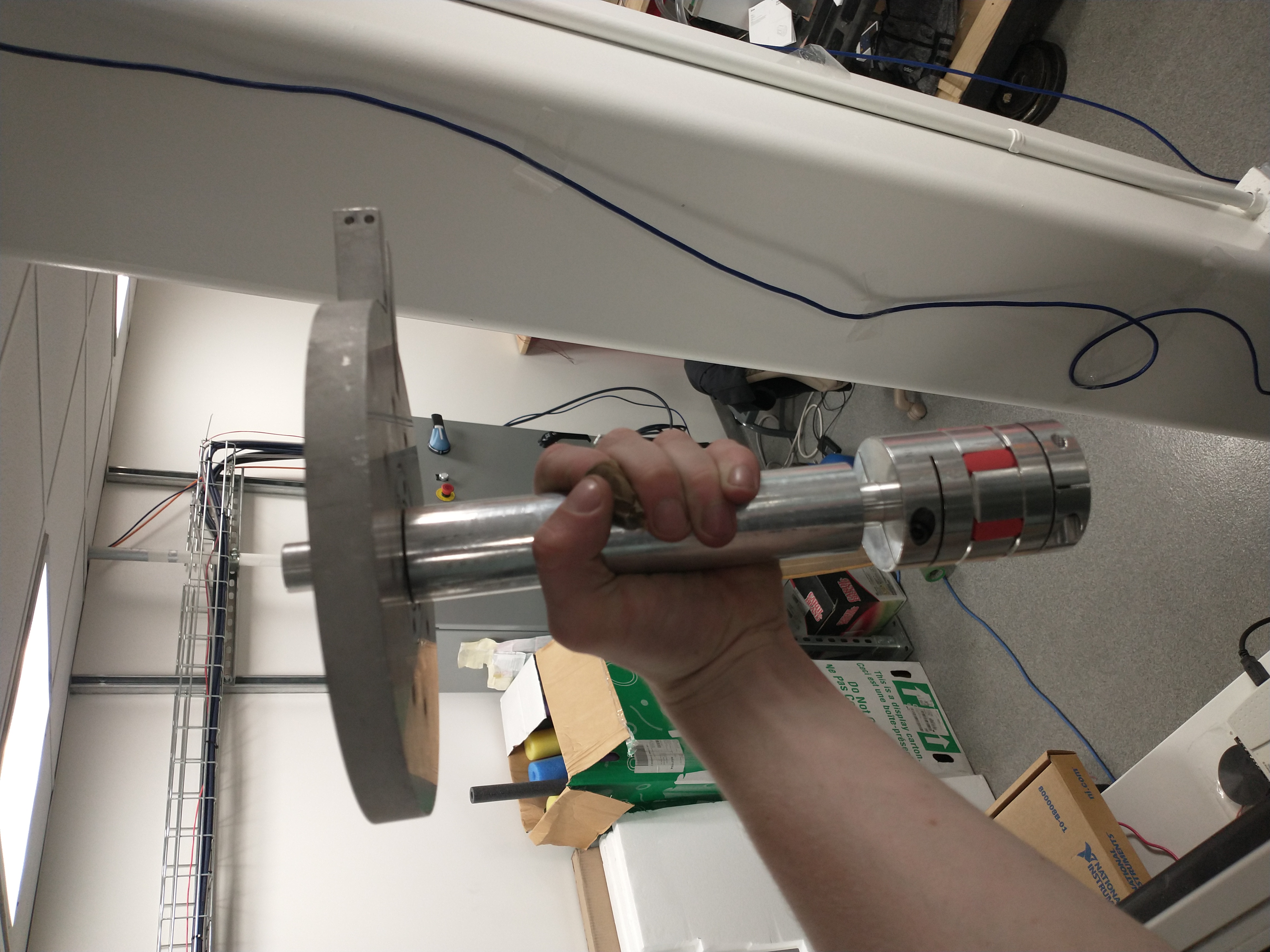
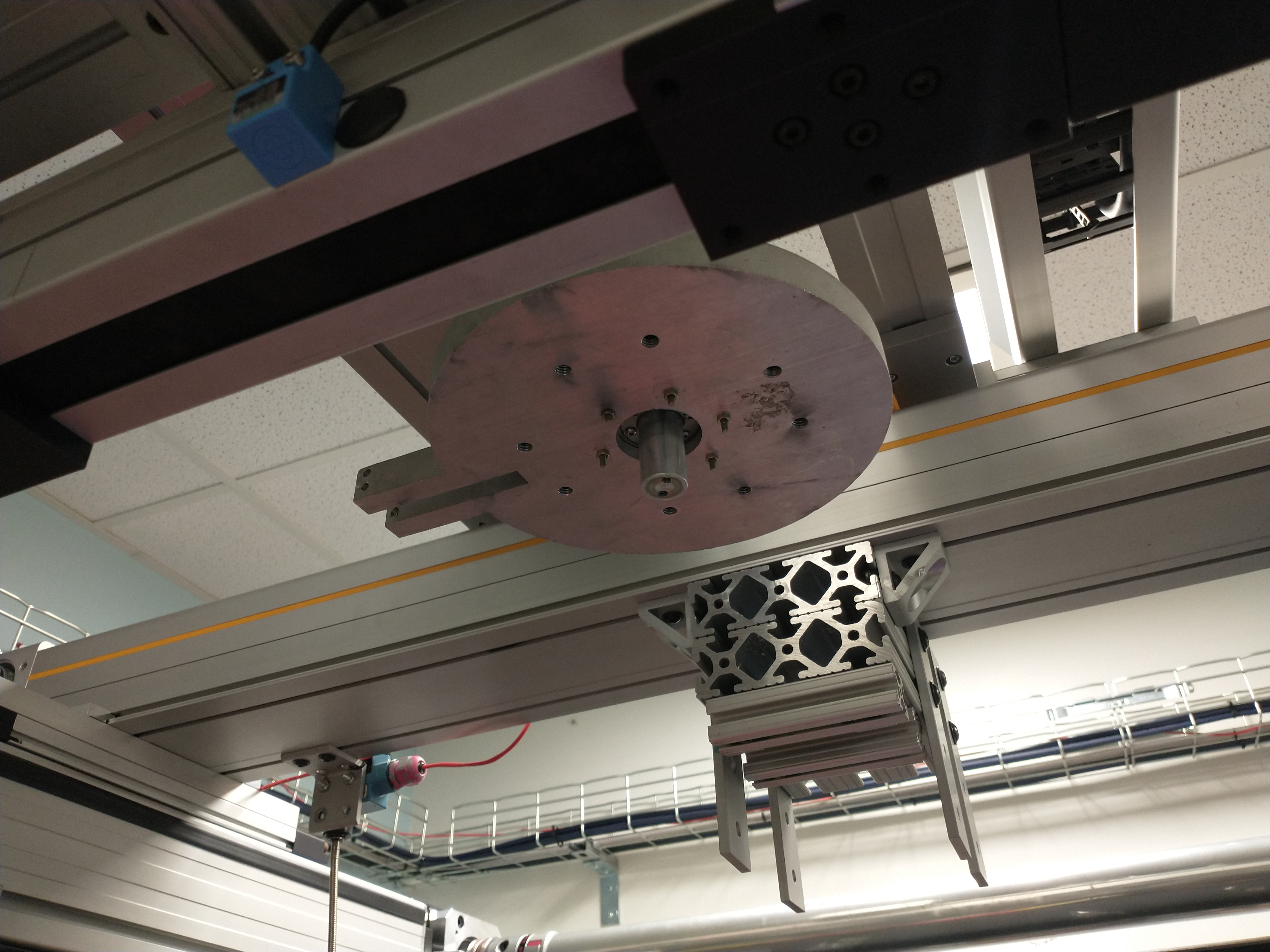
And here is the correct rotary axis setup. I didn’t actually fabricate anything here, just dug through bins of parts and figured out what I thought probably went together. I did add a small limit switch and indicator for aligning the Z axis as the actual limit switch wasn’t working.
Foil Attachment#
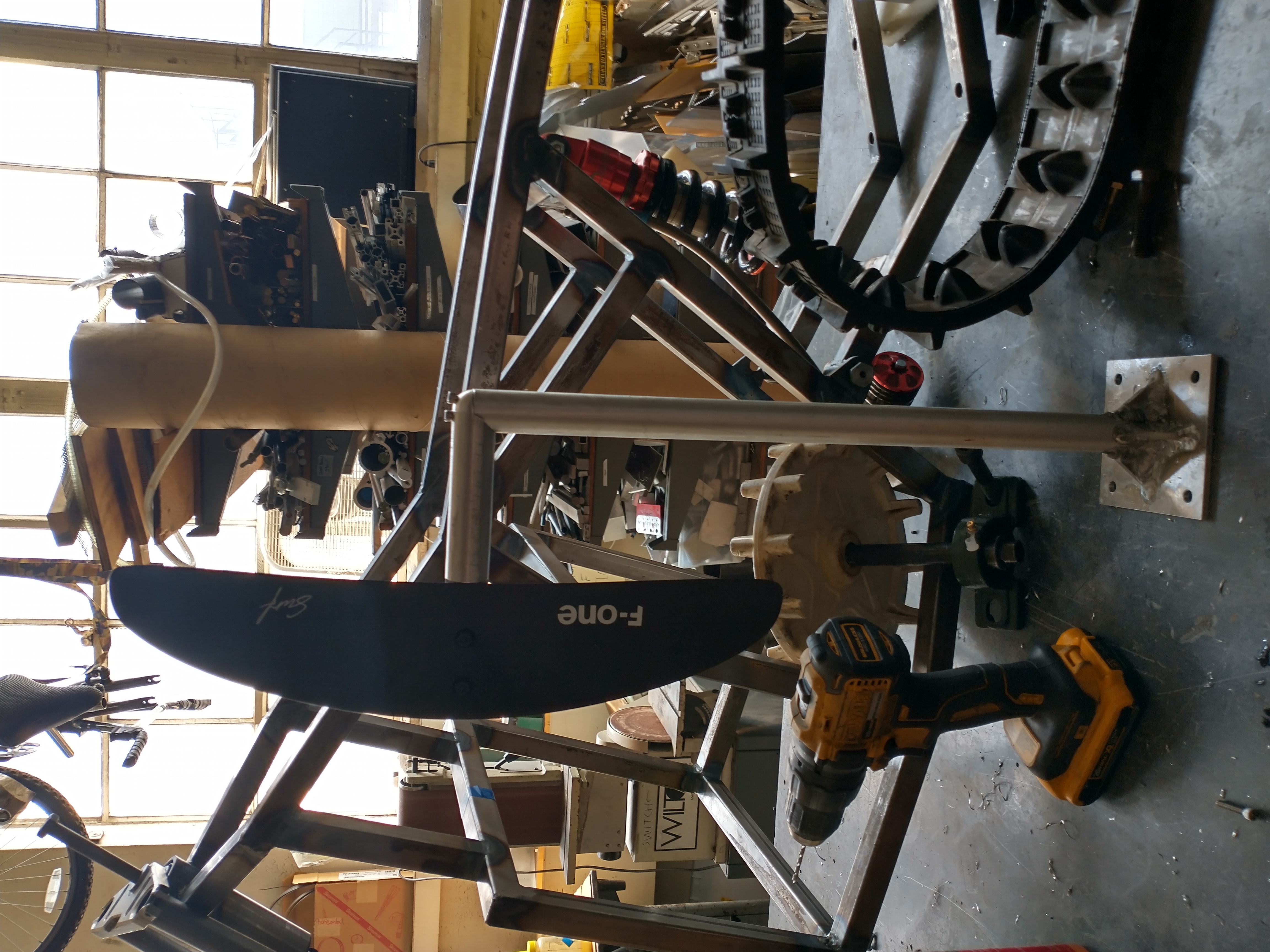
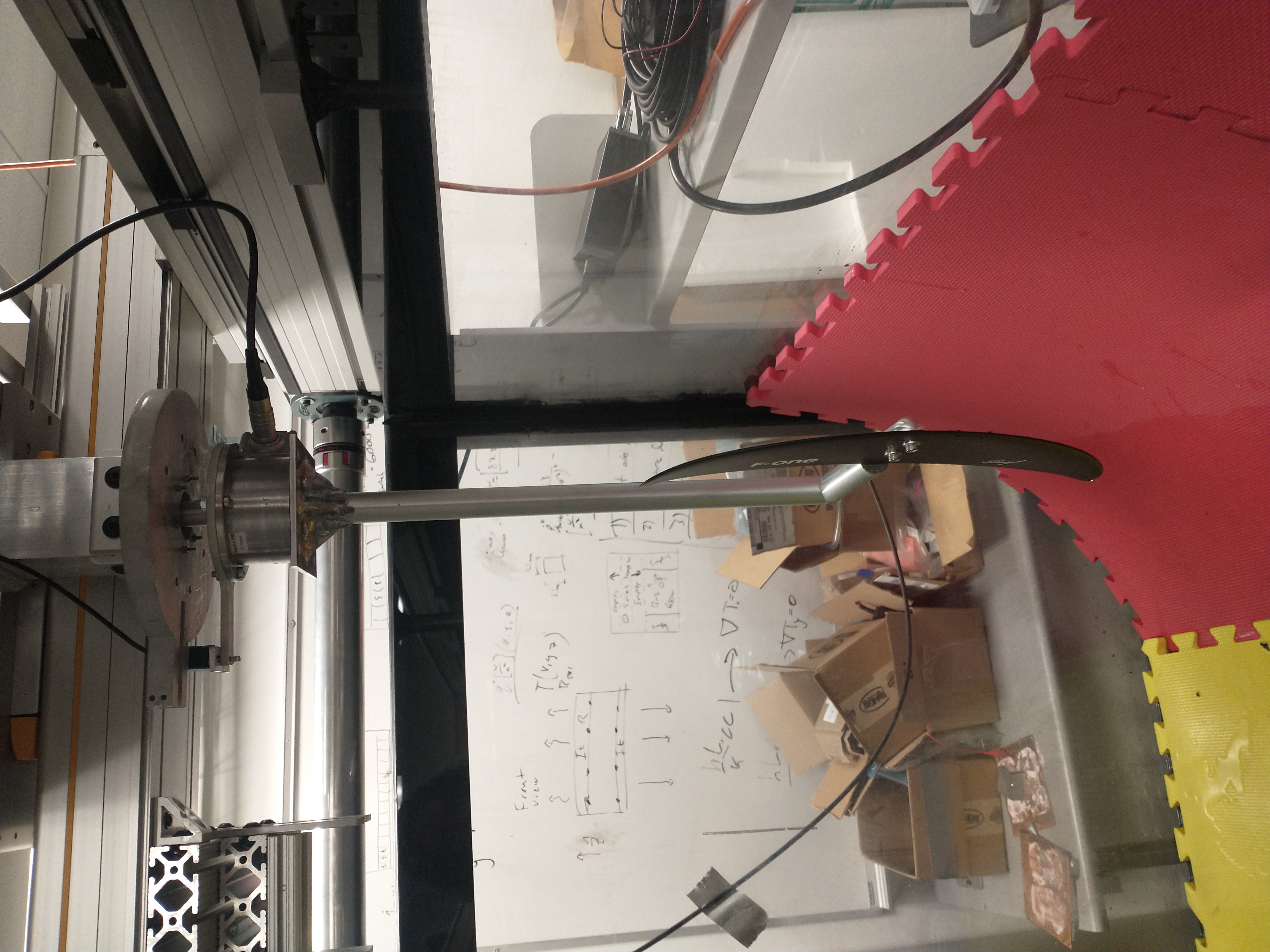
The towing tank isn’t tall enough to accomodate a full size hydrofoil. The wing tips start to interact with the boundary surface of the air/water interface and the bottom of the tank. This kills what are generally called “3D drag effects”, basically the vortex drag caused by fluid flowing around the wingtips. Fortunately, scale models of hydrofoil already exist, the “stab” (rear stabilizing foil) of a foil board. I machined and welded a mast to attach to the load cell, which itself was mounted to the ned of the rotary axis.
Lab Report#
Results and Analysis#
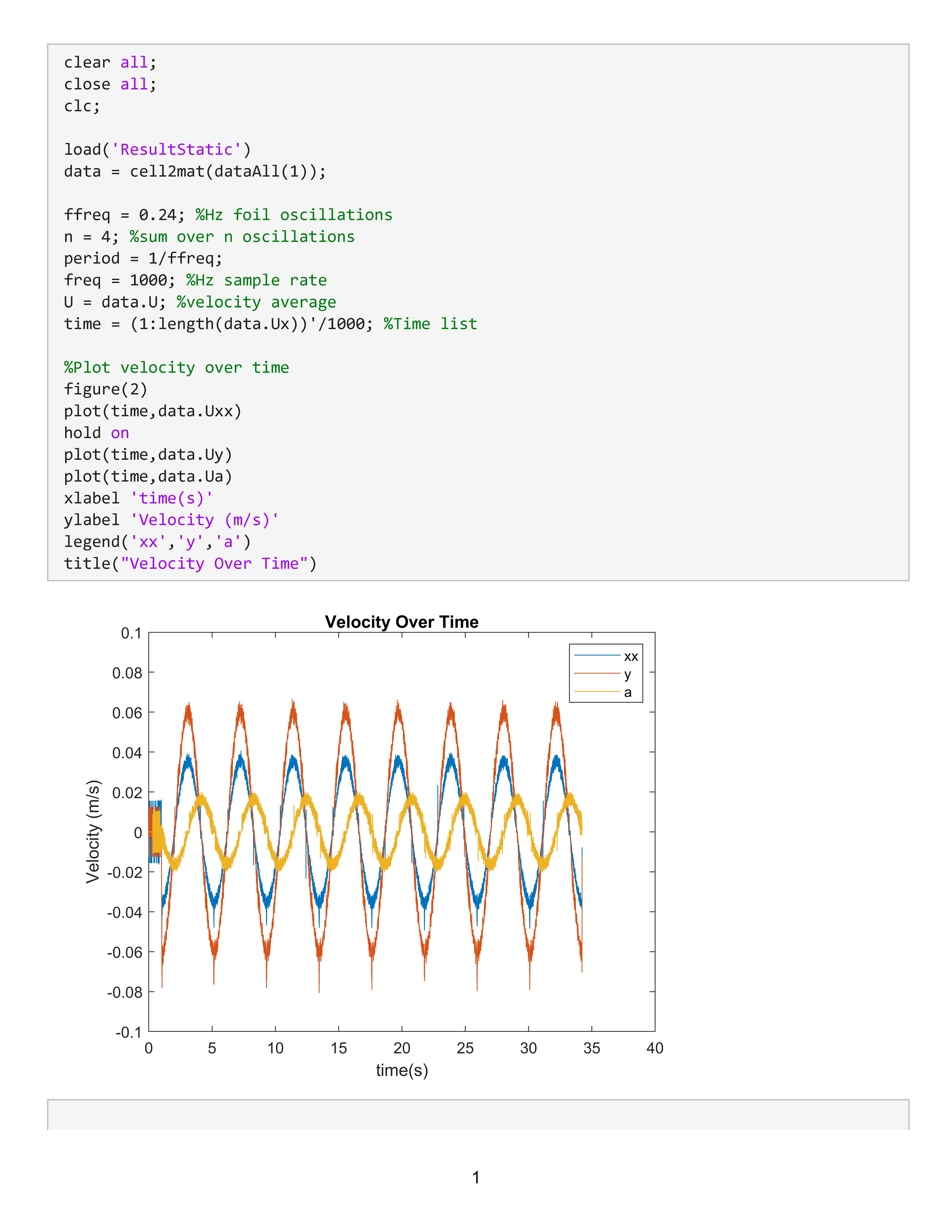
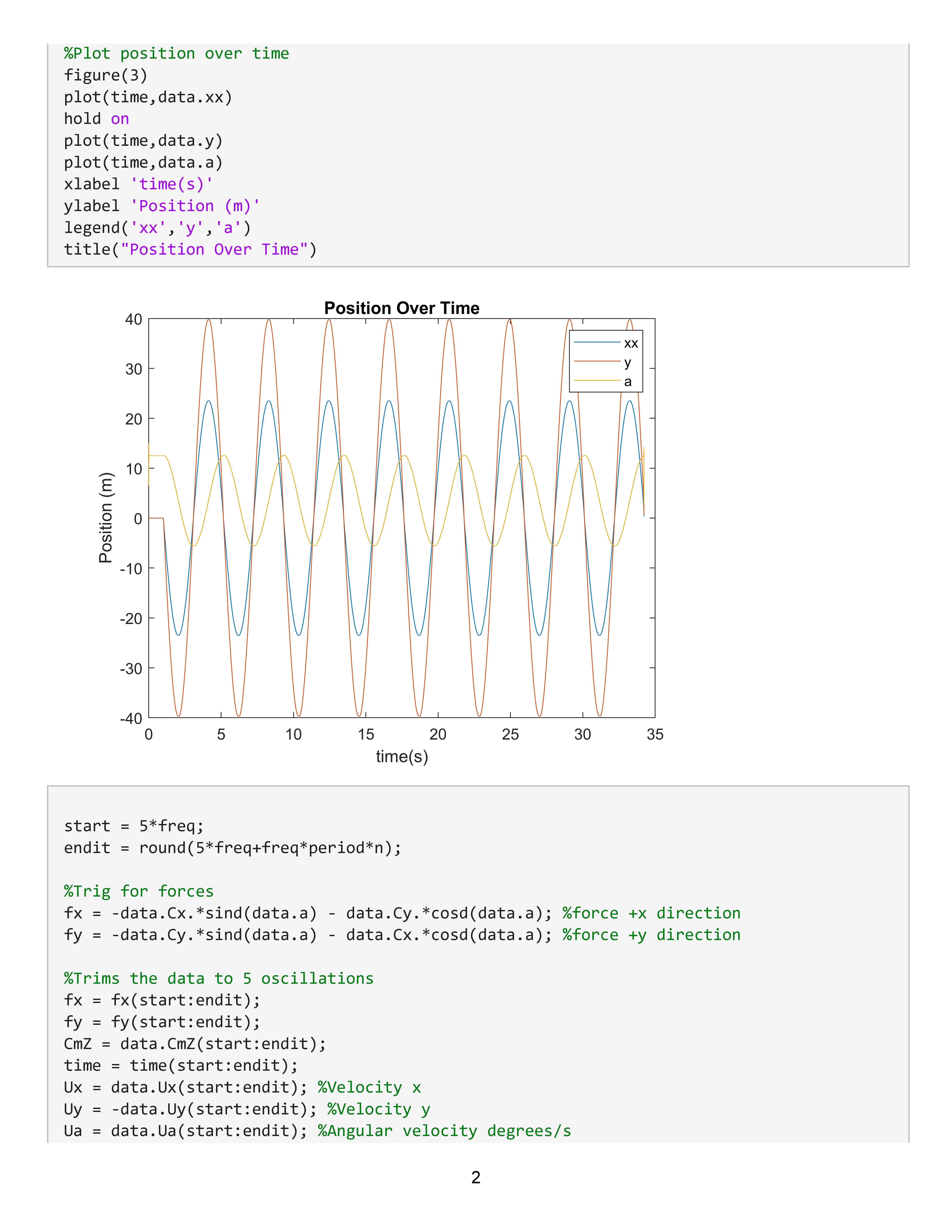
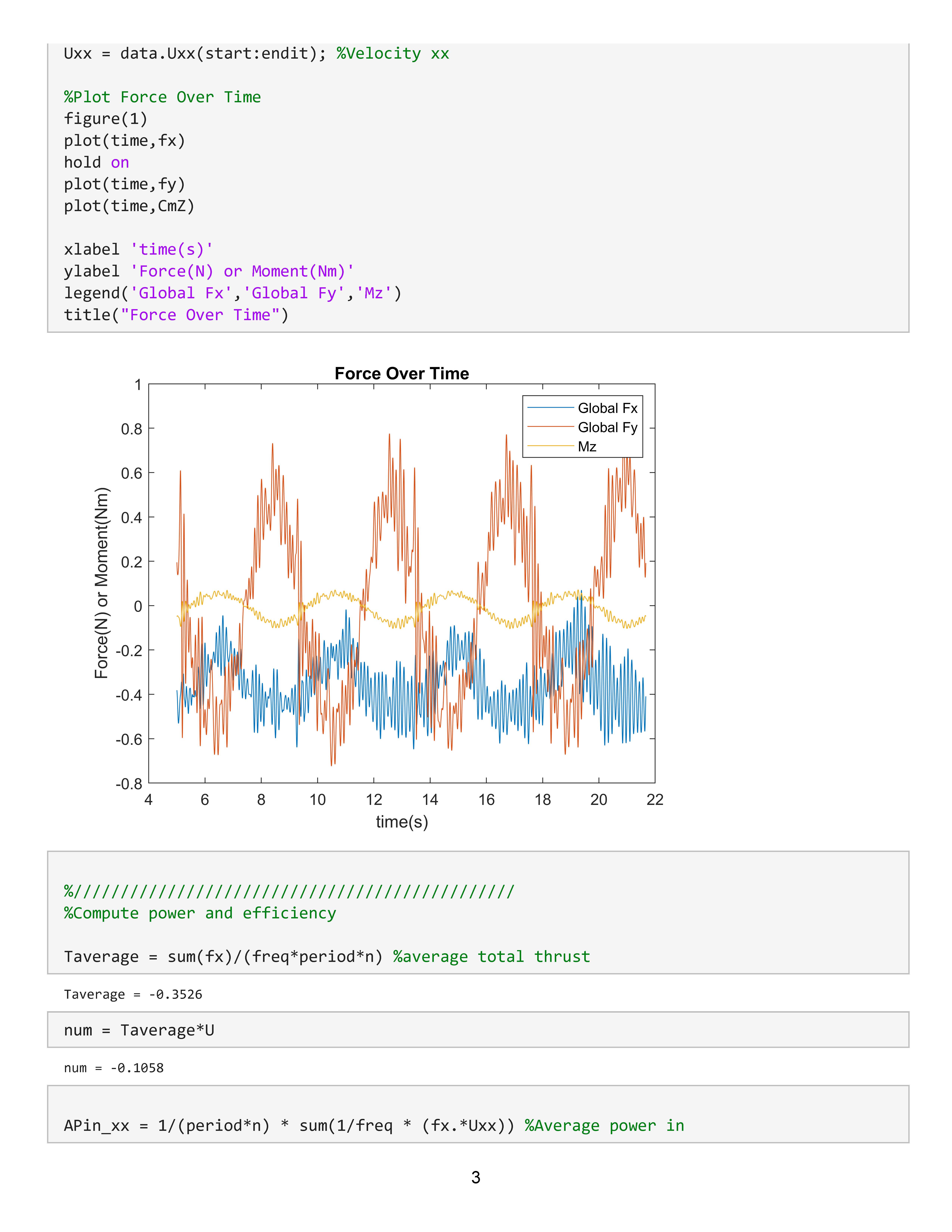
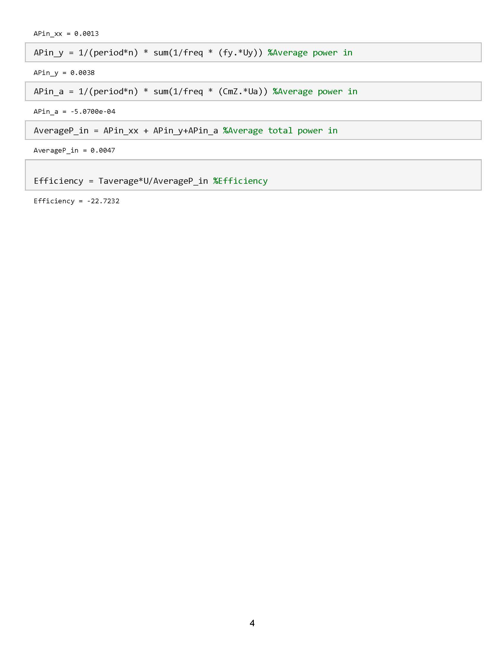
Perhaps the issue here is obvious, but if not I would point out that a negative twenty two percent efficiency doesn’t make much sense. This suggests the foil is creating drag, not producing thrust.
Conclusions#
So what happened? Why is flapping a foil producing drag instead of thrust? The most obvious is that there are some scale changes and this combined with the cylindrical, high drag profile of the attachment results in a drag force greater than the thrust force.
There’s a few ways I attempted to deal with this, though they both suffer from the same issue. Firstly, the drag on a cylinder is generally well understood and can simply be calculated. This is somewhat confounded by the changing water levels in the tank resulting in more or less of the attachment exposed. It is also only easily calculated in smooth flow, whereas it is likely affected by the downwash from the hydrofoil ahead of the mast. Secondly, it is possible to simply run the hydrofoil attachment through the same motions without the hydrofoil mounted. This is confounded for the same reason: the flow experienced by the attachment is different without the foil in place.
Were I to repeat this, I would use a longer fuselage to attach the foil to the attachment mast to avoid flow interference.
Last Updated: September 26, 2026